~vivienne
flyback + MC34063 based power supply
In the very very early stages of designing the first verson of my geiger counter, I had initially wanted to base the design on a flyback transformer and an MC34063. MC34063 is not a very good IC, the hysteretic control makes it very noisy, and the BJT switching transistors waste power, but its otherwise almost exactly what I implemented by using only one IC. Plus, it has current limiting. It has downsides in my application too, particularly the fairly low voltage permissible on the collector of the switch, but in theory I should be able to get away with it by using a flyback transformer. Another downside is the much lower maximum frequency.
Ultimately, that early on, I was never able to wrap my head around it. Now, I feel as though the design equations offered on the datasheet are misleading. After playing around with some weird ways to use a 555 timer, I felt a lot more confident about doing whatever I wanted with an IC as long as it fit the description of what the IC was supposed to do, regardless if that use is prescribed. That’s what I’ve done here.
My goal in this experiment was to create 50 volts-ish DC (extremely low tolerance here, this will become relevant when I get to feedback) from a 5V input. I picked an arbitrarily high maximum frequency within the MC34063s capabilities, 80kHz.
Before I talk any more, here is the schematic, so it is easier to follow along. I will call attention to the feedback network now: using zener diodes this way did not work very well. I will explain why I tried this and why it sucks later in this report.
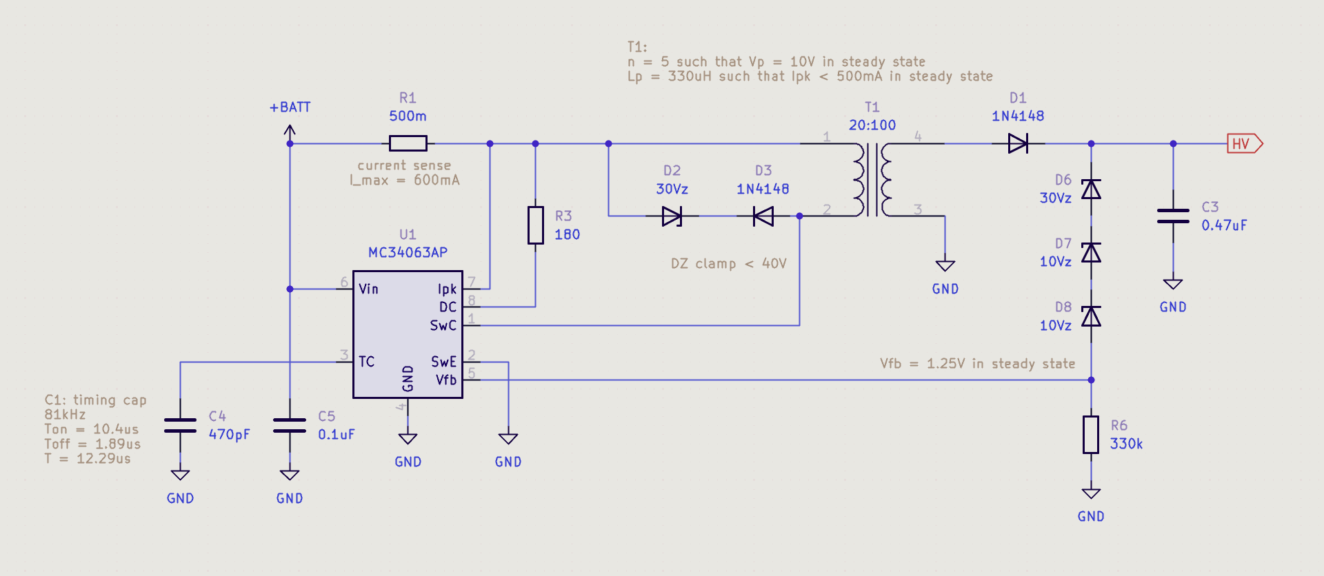
So, starting with the timing capacitor C4. The maximum duty cycle of the MC34063s oscillator is fixed at 85%, which may be measured with a scope. So, the on time at 80kHz may be found by Ton = 80kHz−1 × 0.85 = 10.6us. Then, from the datasheet (and the only formula from the datasheet which I found to be useful), the value of the timing capacitor is found by CT = 10.6us × 4.5E−6 = 478pF. 470pF is the closest standard value, so calculating the actual on time with a 470pF capacitor, Ton = 470pF ÷ 4.5E−6 = 10.4us. The on period is then T = 10.4us ÷ 0.85 = 12.29us, and the new switching frequency is f = 12.29us-1 = 81kHz. We will use these values from this point.
At this point the flyback transformer T1 could now be designed. The two important parameters were turns ratio, which had to be selected such that the voltage on the primary in steady stage was safely within MC34063s specifications, and magnetizing inductance of the primary, so that peak current during the switch on time was controlled. With an output voltage of 50V. These values, as far as I was concerned with this experience, could be pretty much anything that fit those criteria, so it was really just a matter of optimizing so that the turns on the primary were arbitrarily high, but not so high that for some arbitrarily high turns the secondary wouldn’t be able to fit on an EE13 bobbin, which I was using. Winding 20 turns on the bobbin with the ferrites inserted gave me an inductance of approximately 330uH. Peak current in the inductor could then be found as (5V/330uH)10.4uS = di = 157.58mA. A turns ratio of n = 5 gives a 100 turn secondary. This means that when there is 50V across the secondary, there is 50 ÷ 5 = 10V across the primary. Good!
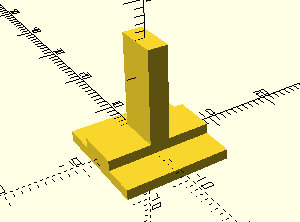
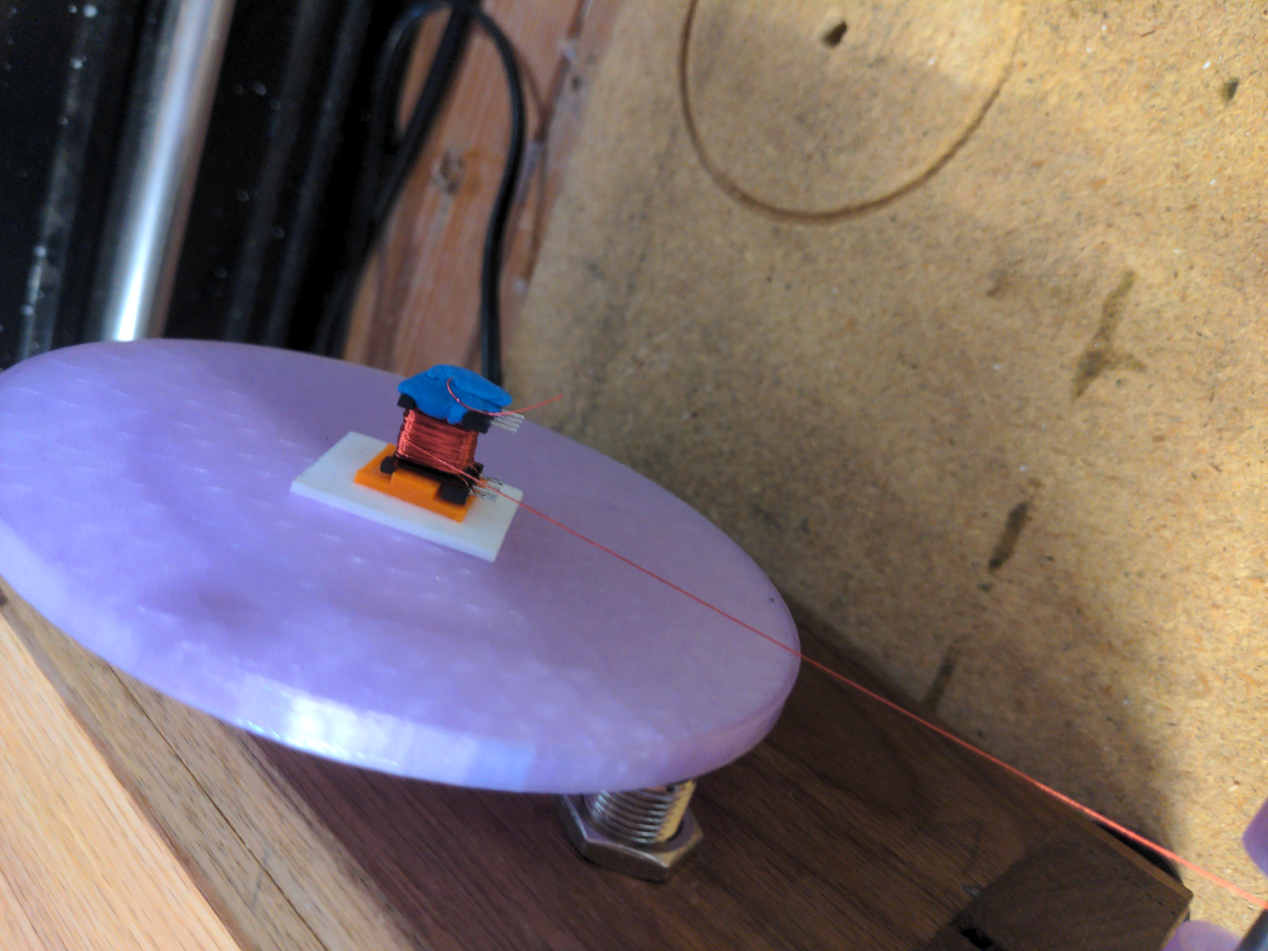
I wrote a little OpenSCAD model to hold the bobbin onto my SO’s guitar pickup winder. The pickup winder was designed to have stuff stuck with double sided tape, but the shape of the bobbin is too awkward. There is a large flat side on this to stick to the winder.
linear_extrude(1.5) square([15, 6], center=true);
linear_extrude(15) square([2.8, 6], center=true);
translate([0, 0, -1.5]) linear_extrude(1.5) square([15, 15],
center=true);
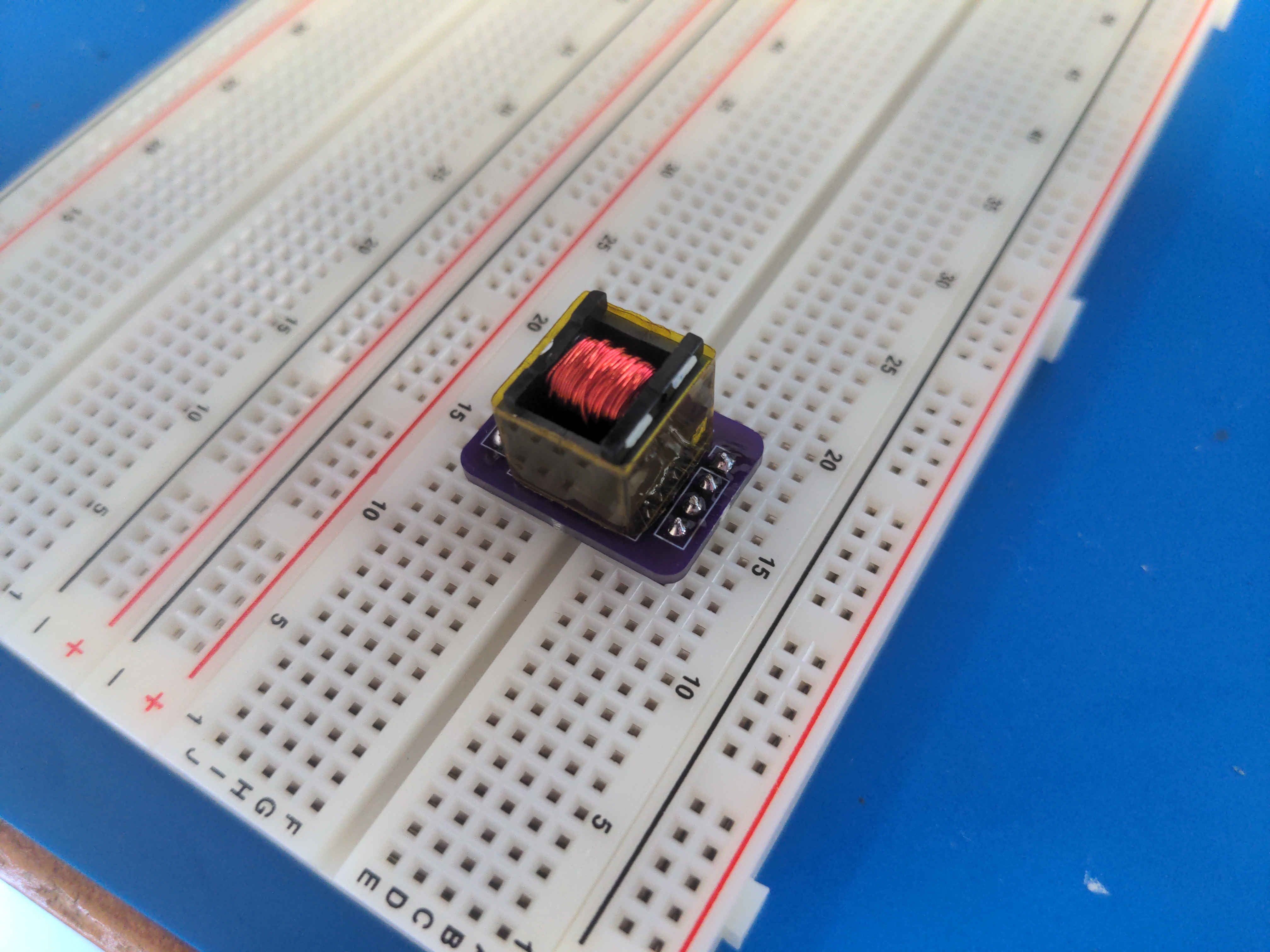
I also made little breakout boards so that I could fit them into a breadboard more easily, and ordered them from OSH park. These boards were so small that even with OSH parks speedy service, it was cheaper to order from them than from JLCPCB.
The KiCad files for this board may be downloaded here.
Interestingly, but not particularly unsurprisingly, the inductance measured by my LC meter changed after winding the secondary:
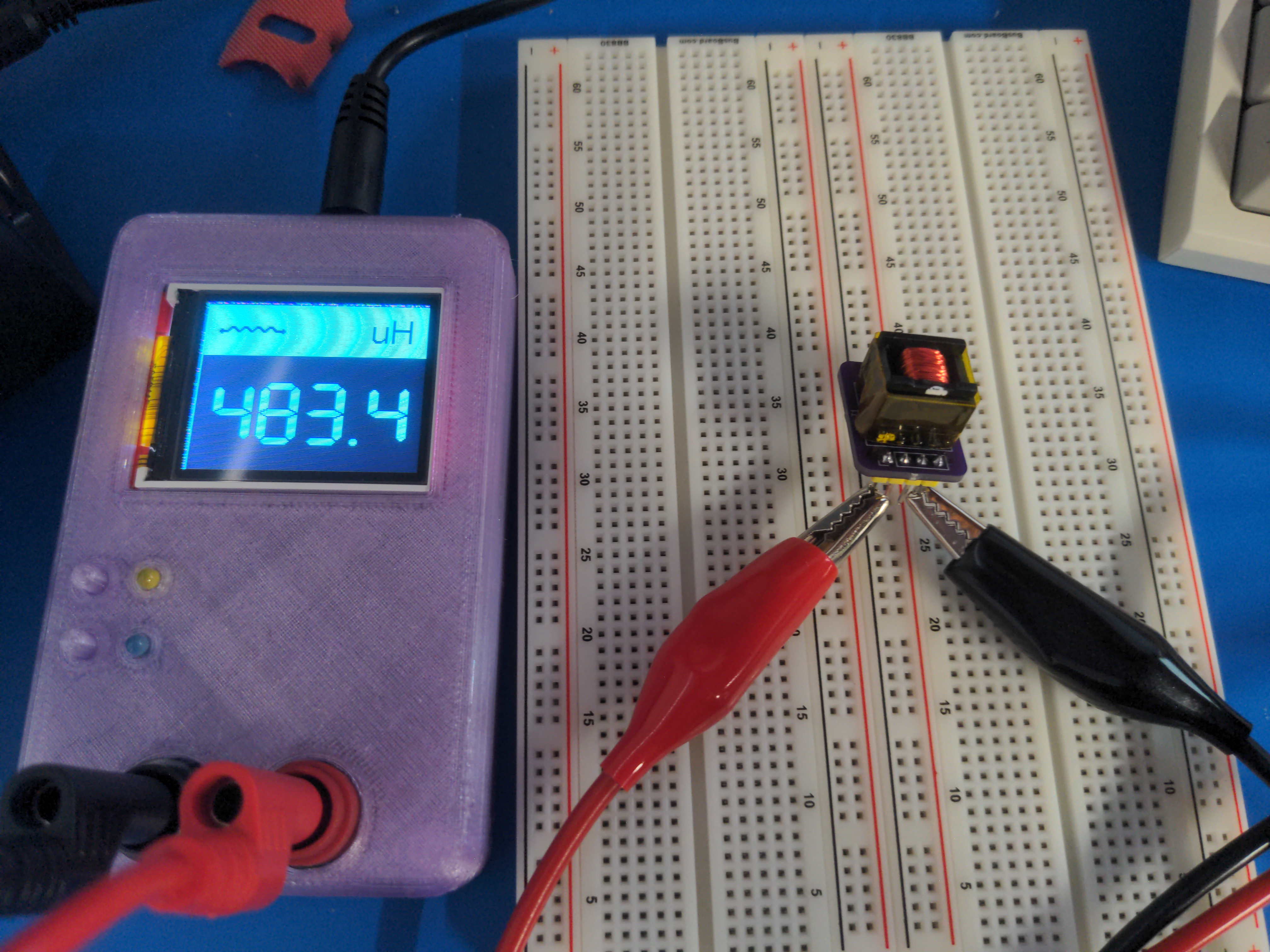
I continued under the assumption that Lm = 330uH, since I don’t really know what the actual magnetizing inductance is anymore. It is fine if it is higher, but it is not fine if it is lower. 330uH is the minimum that it could be, so it is a good assumption for my purposes.
The next step at this point was to select a value for the sense resistor R1. MC34063 detects the voltage across the sense resistor in order to provide current limiting. If the voltage on Ipk increases beyond 0.3V, it begins to shorten the duty cycle of the oscillator, shortening the on time. This is especially important during startup, since at that point output capacitor C3 is empty and presents a short circuit, causing a huge inrush current if unlimited. I selected as the maximum I am willing to tolerate, giving plenty of padding to not slow down startup too much. So, 0.3V ÷ 500mA = 600mΩ. The closest I could get with parts on hand is 500m using two 1 ohm resistors in parallel. Calculating the actual peak current as permitted by a 500mΩ sense resistor, 0.3V ÷ 500mΩ = 600mA. This is fine.
Next is the DZ clamp across the primary. Any real flyback is non ideal, and exhibits a leakage inductance, which will cause an inductive spike. This has to be controlled to be within the maximum Vceo of the switching transistor. The voltage at the collector will be clamped within the breakdown voltage of the zener, plus the forward voltage of the other diode, plus Vin. Selecting a zener whose Vz = 30V is sufficient here. It is important that the DZ clamp does not clamp the the voltage which comes from the output voltage of the power supply over the turns ratio, or it will clamp the output too!
Finally, the feedback. This was a prototype for what would eventually be a 400V supply for a geiger counter. In geiger counter power supplies, if you are to take resistive feedback from the output, the feedback network needs to have an extremely high impedance if you don’t want the power dissipated by it to dwarf the power consumed by the tube. Here, I experimented with using zener conduction to be a very loosey-goosey tolerance feedback network, since geiger mueller tubes have a very very wide range of voltage which they can tolerate. When out of regulation, there is effectively no current through the zeners at all. When in regulation, the current through the zeners would be the voltage at MC34063s Vfb pin in steady state and the resistor R6, or I = 1.25V ÷ 330kΩ = 3.79uA, and the power dissipated would be P = 1.25V2 ÷ 330kΩ = 4.7uW. That sounds pretty good!
Here’s what it looks like all put together on my breadboard. Messy, but its just a prototype.
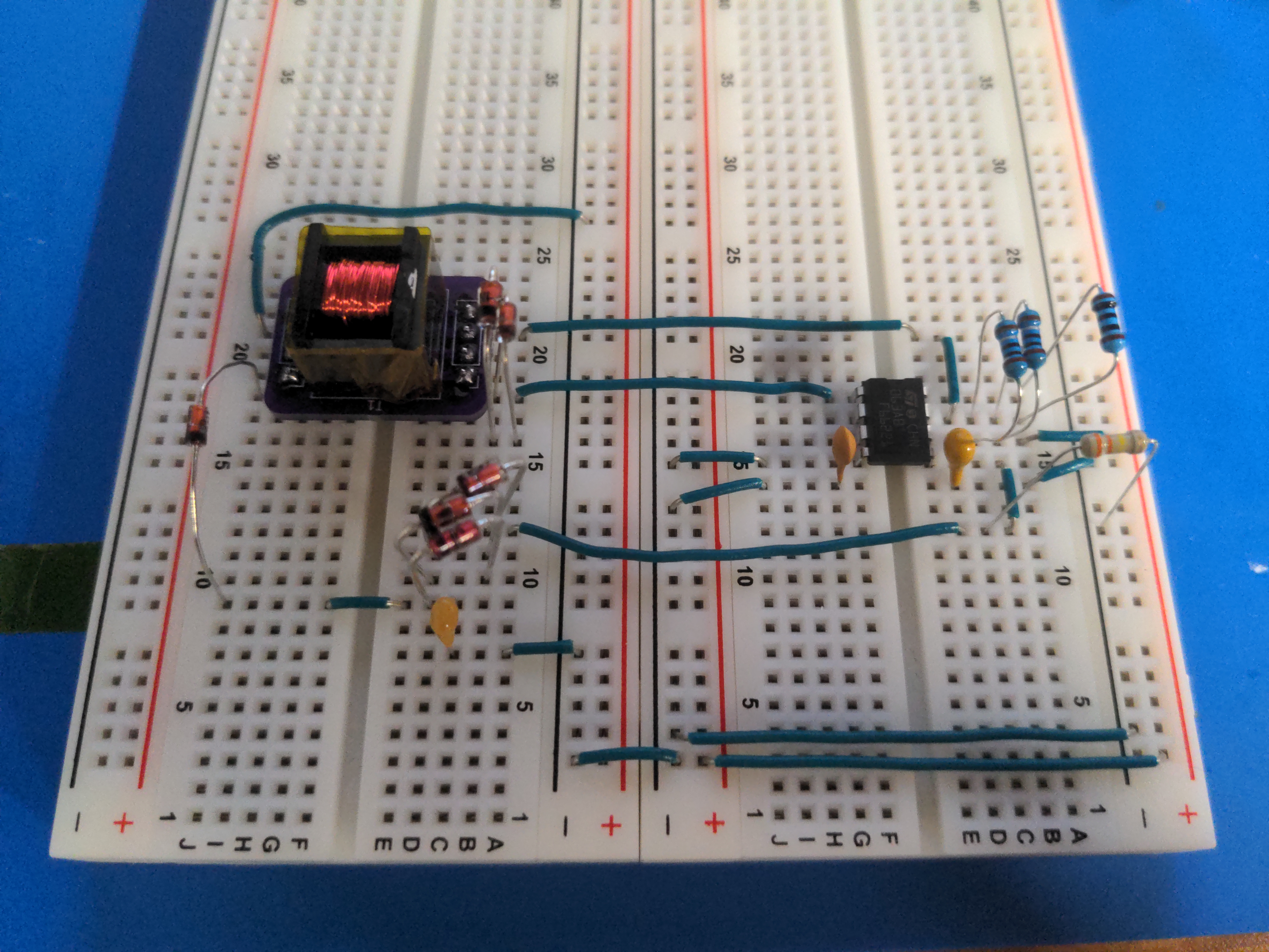
And it worked!
Now, there is a lot of background noise in the video, but you’ll notice when I plug the thing in, the sound from the transformer is not very nice. The sound itself is benign, that’s just magnetostriction on a not very tightly wound bobbin. But the character of it is interesting. Its short bursts with large periods inbetween. It turns out that with regulation taken like this, MC34063 likes to run the output in bursts. This is very bad, because it means the switching frequency is all over the place, and ripple is huge. Okay, I knew I was fine with the ripple being big because of the range I can handle on my load, but the switching frequency bothers me because that means noise all over the place. But this works! It is also much better behaved with a normal resistive feedback, so in my real implementation I will be using that instead.